Low-Cost Cycling Power Meter Build
Introduction
As an active cyclist, I was searching for an inexpensive solution to measure my power output on the bike. I was seeking a more precise method of tracking my efforts than a heart rate monitor and a power meter stuck out as the best option. Shopping around for a power meter led me to find that the price range was $500 for a lower end or single-sided power meter, all the way up to $2000 for a top-of-the-line model. After seeing this price range, I was determined to create my own for less than $100. The total cost of parts for this prototype sits at $59.12. I have currently spent 120 hours of my time on this project in an effort to optimize it as fully as possible.
Strain Gauges
I knew that I could make a power meter myself after doing some research into the functionality. At their core, cycling power meters measure the torque through strain gauges and the cadence via an accelerometers and multiply the two to calculate total power. The first step of the process was to mount the strain gauges on the crank of the bike. For testing, I was using a stationary spinning bike to simplify the prototyping process.
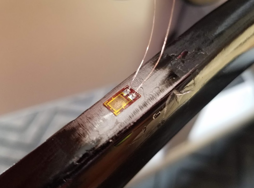
Mounting of the first strain gauge
Initially, I mounted only a single strain gauge in a wheatstone bridge configuration with three equivalent resistors. This proved to be inaccurate as the resistors were unstable and the tolerances of manufacturing resulted in the wheatstone bridge being in a constantly varying state of unbalanced resistance. I solved this issue by mounting four strain gauges wired together in a wheatstone bridge configuration.
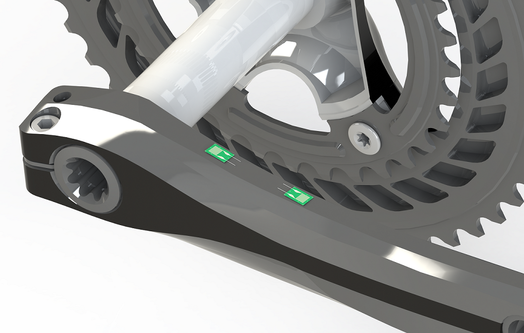
Position of the strain gauges mounted on one side of the left crank arm
Amplifier
The signal to be produced by the strain gauges was on the order of milliohms, so an amplifier was required. After researching the various amplifiers sold by companies such as Sparkfun and Adafruit, I settled on the HX711. This board has an excellent track record with measuring small-scale strain in projects similar to mine. I made a small modification to the circuitry of the breakout board to enable a 80Hz sample rate instead of the default 10Hz sample rate.
Motion Processing Unit
The ability to accurately sense the pedaling cadence was vital to the success of this project, so I selected the MPU6050 as the device I would use to measure the rotational speed of the crankset. I chose the MPU6050 due to its ability to digitally process the outputs from both the 3-axis gyroscope and 3-axis accelerometer to give a more accurate reading of yaw, pitch, and roll.
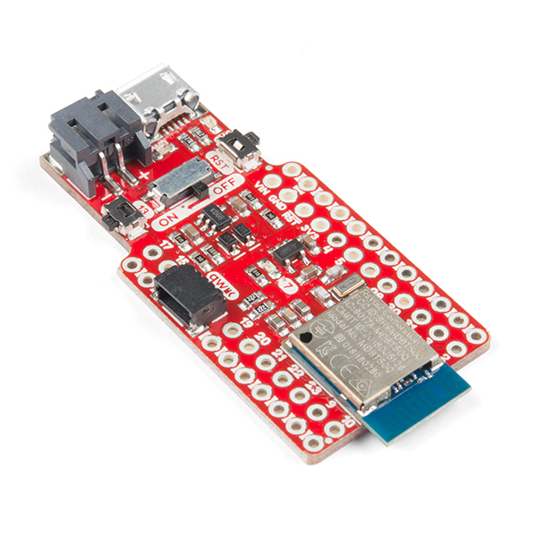
Microcontroller and Bluetooth Low Energy Communication
The data I was collecting from the strain gauges and MPU6050 was useful, but I wanted to be able to transmit the data live using the Bluetooth Low Energy protocol for use with Zwift, Strava, and Garmin and Wahoo bike computers. I chose the SparkFun Pro nRF52840 Mini for this as it had the GPIO pins needed to interface with the HX711 and MPU6050 as well as an integrated Nordic Semiconductor nRF52840 chip which would allow me to communicate over the 2.4Ghz Bluetooth spectrum. The associated Bluetooth protocol communication took many many to test and retest to assure compatability with Zwift, Strava, and bike computers. The documentation was acceptable, but examples using the SparkFun Pro nRF52840 Mini were nonexistant. The finished product transmits the power output as well as cadence following the specifications given by the Bluetooth protocol.